

We get technical with Super-enthusiast, Jon Stoodley of JSE Trials in Muskogee, USA – here are Jon’s ‘GEARHEAD ALERTS’ – a series of useful technical and tuning tips for the trials enthusiast.
Jon Stoodley has been around the sport for a long time and isn’t frightened to put back in what he took out of the sport as a younger man.

INDEX
001 – Flywheel weight and kickstarting a trials engine
002 – The taper on the shaft
003 – A clean shop is a healthy shop!
004 – Reed Valves and induction
005 – Combustion Chambers and the Pumping Loss
006 – Porting Part 2
007 – Porting Part 3
008 – Pistons
009 – Two-stroke scavenging
010 – Drain Plugs and sealing washers
011 – Squish Bands
012 – Gas Gas 2002 Pro Clutch
013 – 2002 Gas Gas Pro Set-Up Tips
014 – Lubrication
015 – Carburation
Read on!
Gearhead Alert 001:
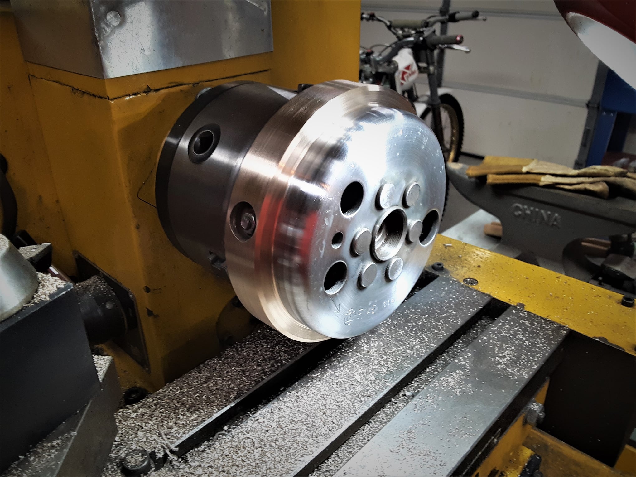
Flywheel weight and kickstarting a trials engine:

I’m going to talk on a very ‘weighty’ subject, namely Trials flywheels. This flywheel is for the 1976 Yamaha TY250 twinshock engine that will be ridden by an Expert/Master rider and I am taking off some weight to make the power delivery a little more responsive to suit his riding needs. The flywheel weight was installed by the factory a little cockeyed and the machine work will fix that.
Most TY twinshock and Mono engine flywheels I’ve modified have a steel band added but this particular engine had a bronze band and as I remember, bronze is about 10% heavier by volume than steel. On the subject of flywheels, lets talk about how you start your bike.
We stop and start our bikes during a Trial more than any other motorcycle competition and I see a lot of riders stomp down on the kickstart lever and this can cause damage to the kickstart mechanism. Trials engines have massive flywheels and high compression which makes the crank VERY resistant to start turning and when you stomp on the lever without taking up the slack in the ratcheting mechanism, it slams the parts together and causes damage over time. I advise riders to start a Trials engine just like you would start a V-twin Harley.
You don’t stomp on the kickstart like you would a RM125 with a tiny flywheel, you take up the slack in the kickstart, raise up and use body weight to get things spinning.
Your engine, as well as your pocketbook, will thank you for it!
Jon Stoodley – JSE Trials – Muskogee
Gearhead Alert 002:
The taper on the shaft
While we’re on the care and feeding of the Yamaha TY250 ignition flywheel, we are going to look at a very, very important part of the assembly that very often gets ignored as it is usually hidden from sight. This is the tapered end of the crankshaft (often called a crank “stub”) that the flywheel mounts on. A very common misconception is that the little half-moon shaped key that fits in the slot on the taper (also called a ‘Woodruff key’) is what keeps the flywheel from slipping on the spindle – not so! It’s only job is to align the flywheel in it’s special spot (‘index’) on the crank when re-installing the flywheel.
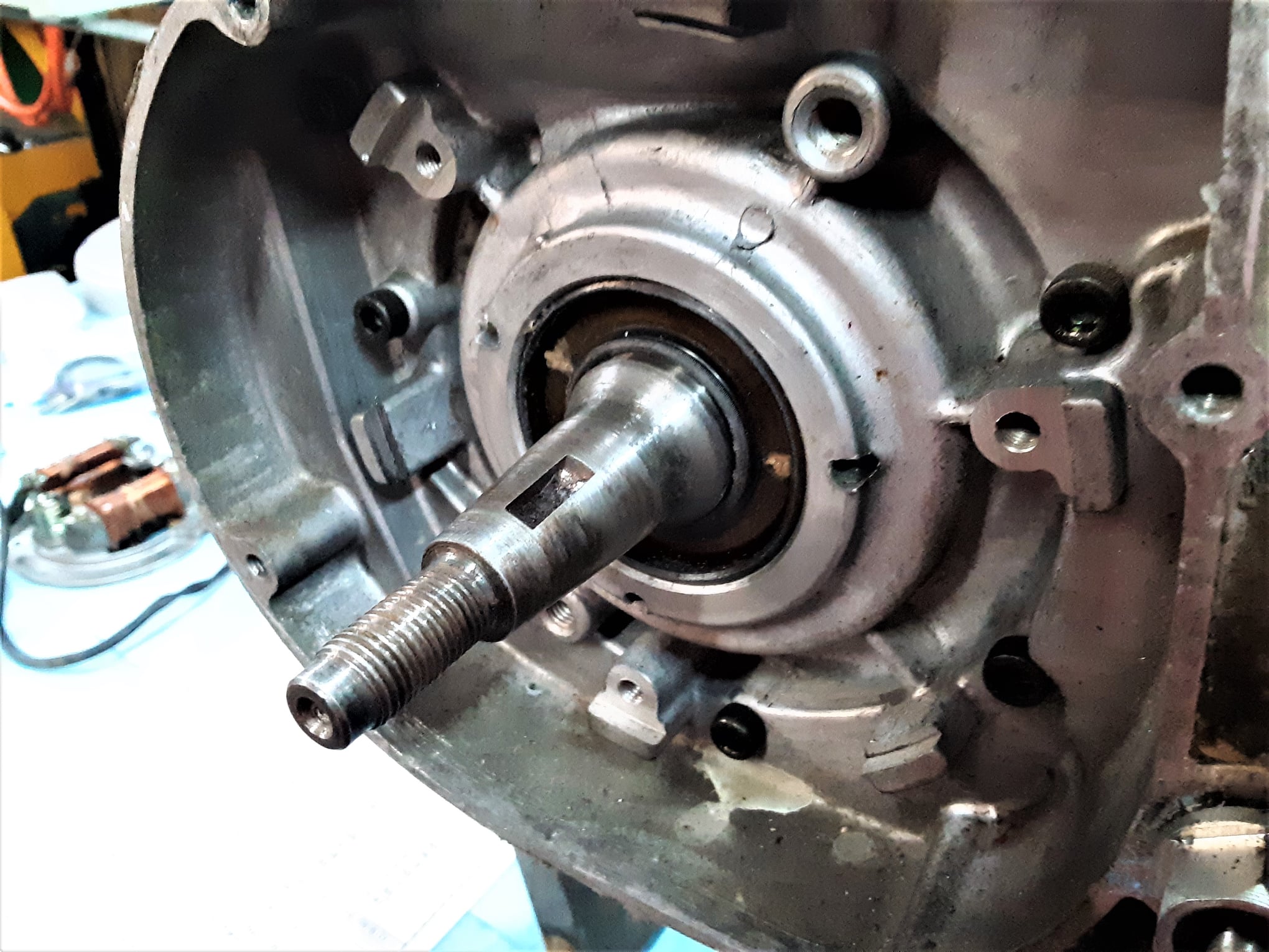
What keeps the flywheel tight is the taper on the crank stub sticking in the flywheel hub (also tapered)? Ever have two tall, smooth sided plastic drinking cups really, really stuck together? The concept is the same. There are a lot of different ‘machine tapers’ and I use them a lot, for instance on my lathe and mill, to change tools and bits. Mine are what’s called ‘Morse Tapers’, in my case the #1 and #2 sizes (‘MT1 and MT2’) but I also use a ‘Jacobs Taper’ when I change drill chucks and centering tools. They are very handy. I first learned about machine tapers as a 15 year-old with mt first car, a 1946 Ford that used a Morse taper to hold the brake hubs on the rear axles. They were a constant pain as I, being a hard-core, goofball ‘Gearhead’, constantly messed with the engine to get more power, which in turn, totally overpowered the ability of the tapered hub to keep contact with the axles. I changed axles and hubs often – So, what we have here on the Yamaha TY spindle is probably a Morse taper of the ‘self-releasing class’, which means is that it requires a device, in this case a threaded piece at the end of the taper with a nut to hold it stuck together tight (my lathe uses the same type device called a “drawbar”). Keeping the flywheel stuck together as tight as required can be a problem particular to Trials engines. Let’s look at what happens when the fastener becomes loose and the flywheel hub spins on the stub and shears the Woodruff key in half. The hub scrapes along the shaft and gouges the surface, destroying the smooth machined finish and greatly reducing the contacting surfaces that are required to hold the pieces together.
In the case of this TY, there is some evidence of that happening one time but the damage is not too bad and some light dressing of the surface should repair it. If the damage is worse (and I have seen some pretty chewed up spindles), the tapers ability to hold together is greatly reduced and chances of the flywheel coming loose again is in the near future. The symptoms of a flywheel key shearing and the flywheel moving on the spindle is the engine won’t start and sometimes the engine will backfire, depending on where the flywheel moved to as it affects ignition timing and the reason the flywheel uses the Woodruff key to index the flywheel’s position on the crank.
One of the temporary fixes (it will never be as good as new) is to use valve grinding compound to “lap” the hub and spindle together. In a pinch, I have also used very, very thin sheets of brass (called ‘shims’) cut to surround the taper so when the hub is installed and tightened, the brass deforms to fill in the nooks and crannies on the spindle and in the hub, locking them together. It works like glue would only that being metal, it is more solid and not effected by heat. Now, how in the heck do these things come loose?
An engine goes through ‘heat cycles’ in use, the getting hot and then cooling down which results in a lot of expansion and contraction of the materials it is made from. This tends to cause fasteners to loosen up over time. As far as motorcycle competition is concerned, a Trials engines is subject to this process more than any other competition engine. This is also why you need to check the torque setting on the flywheel now and then and also why you should check all the other fasteners on a regular basis if you are concerned with finishing an event. Another thing is the Trials flywheel mass is greater than any other types of competition flywheels. They come in handy when climbing a slippery obstacle which is why riders rev up the engines at the bottom of a loose or muddy hill (storing energy in the flywheel), take off and then roll off the throttle and let the flywheel energy, rather than engine torque which would tend to make the rear wheel spin, take them to the top.
This flywheel mass also is part of the reason you need to check the fastener now and then. We ride in rough terrain and the rear tire does a lot of stop/start stuff and with the clutch out, the stop/start activity transfers to the engine crank and the flywheel. This causes a lot of twist at the at the flywheel spindle/hub junction so in effect, the flywheel is constantly trying to twist itself off the crank. As far as things getting loose, for instance, lets look at the heads on water-cooled Trials bikes, which often use copper washers under the capscrews to keep coolant from seeping out.
With the heat cycles, the copper, which is softer than the surrounding materials, is gradually compressed and the head is not held on as securely and will result eventually in a head o-ring failure and loss of coolant. This is why a newly assembled engine should be checked and all fasteners re-torqued after 6 or 7 heat cycles, especially the cylinder nuts, the head capscrews and the flywheel. A brand new bike will require re-torqueing of ALL fasteners after a few hours of use if you want it to be reliable. I’ve seen a lot of riders of new bikes experience a part failure and blame the manufacturer for making shoddy products when, in reality, they are the cause because they didn’t take proper care ( or read the directions). Trials bikes are amazingly reliable, which often leads to a “ride hard and put away wet” attitude when it comes to maintenance. I’ve been involved is just about all forms of motorcycle competition and and a modern Trials bike is probably the most “competition purpose-built” piece of machinery right out of the box. What other form of motorcycle competition can you buy a new bike and after a little setup time enter a National event and have a great chance of winning your class. I bet you never knew how cool a Morse taper was, did you?
Jon Stoodley – JSE Trials – Muskogee
Gearhead Alert 003:
A clean shop is a healthy shop!

When I have a project, I get out one of my folding tables to keep all the parts in order and in one place. The tables are strong enough to hold anything I put on them and are adjustable for height. I use small ‘ziploc’ bags to keep the various fasteners together which makes assembly a snap.
The blue paper workshop towels absorb drips, make things not roll off the table and it’s easy to see what needs to be done next. Afterwards, I fold up the extra ‘work bench’ and put it back in the garden shed. I never have to search for parts, I like that!
The engine stand I designed and built to hold dirt bike engines from CR450s to GasGas 125s. It’s super strong, holds the engine solid and has an open bottom for oil drain pans etc. Cases with the swing arm pivot on the back slide right right on and in the case of the early TY type engines, with no swingarm hole, I made attachments to adapt it quickly.

Jon Stoodley – JSE Trials – Muskogee
Gearhead Alert 004:
Reed Valves and induction

When doing some engine work on a 1976 Yamaha TY250 twinshock, I decided to highlight induction. I’m adapting a 26mm OKO flatside carb. Although you can essentially just bolt the carb on, to get it to be really effective and achieve it’s potential, some modifications are called for. Shown is the modified reed cage.
In the stock cage, there are a lot of sharp edges and changes in the cross section area that create turbulence and reduce flow velocity of the incoming air/fuel charge.
Intake tracts do not like abrupt changes in the cross section area and anything you can do to keep the tract as uniform as possible will yield good results.
Most riders do not realize how “busy” intake and exhaust systems are. They do not operate at a constant flow rate but a rapid series of start/stop, pressure/vacuum conditions.
I pay particular attention to the reed tip area of the cage to allow the strongest “signal” (pressure/vacuum) possible for better reed action. I also dress the sharp edges of the new reeds (Boyesen dual-stage in this case) with very fine sandpaper (to eliminate the ‘stress risers’ caused by the sharp edges where cracks start) to reduce the chance of fraying or breakage.If you put the OKO carb in the manifold and tighten the clamp (always take measurements with the fasteners tight) you will notice two things.
First, the bore of the 26mm OKO is smaller than the manifold bore and, second, there is a fairly large gap between the end of the carb and the start of the manifold bore as the OKO has a shorter spigot than the stock carb.
The aluminum ring pictured I machined to fit in the manifold to fill that gap.Some careful hand machining of the OKO spigot bore enlarges it smoothly to the diameter of the manifold. The manifold is smoothed out with any manufacturing mold marks eliminated. So, just a few things you can do to make your engine run better. Trust me, when it comes to engine building, little things add up and it’s the difference between an engine running ‘better’ and one that runs ‘great’!
Jon Stoodley – JSE Trials – Muskogee
Gearhead Alert 005:
Combustion Chambers and the Pumping Loss

I have a great “partner in crime” when it come to off-beat motorcycle projects, Rick Land (AVTA and head of the Land Family Trials team). He has built a beautiful modified Yamaha TY250 Monoshock and I did the engine modifications. Having tested the bike he has run into some jetting issues and has tried all the possibilities we could come up with.
Based on all the evidence, we have arrived at the conclusion that the Secondary compression ratio (the ratio of swept volume of the cylinder to volume of the combustion chamber) is a little too high. This will make jetting a problem as well as encountering ‘pumping loss’ at higher rpm. ‘Pumping loss’ is a reduction of power output caused by the piston expending too much energy compressing the air/fuel mixture just before ignition.
One of the symptoms this engine had was too much power in the mid-range. In a two-stroke engine, when the compression ratio is high the engine will produce great power in bottom and mid ranges but ‘flatten out’ at high rpm even though this TY engine produced very good power at high rpm.
One of the major differences between an outdoor track MX engine and a SuperCross engine is compression ratios. I used the plural as there are two C/R factors in MX to consider, the Primary Ratio (volume of crankcase at piston BDC and crankcase volume at TDC. Actually the measurements involve the port heights but you get the idea) and the Secondary Ratio (volume of swept volume of cylinder to volume of combustion chamber).
The combustion chambers of the 250 TY Mono and 350 TY Mono are quite different. The 350 chamber is a trapezoid shape and the 250 is a modified hemispherical shape (a little more cone shaped).
What we’re going to do is to modify the chamber shape, squishband width and chamber to squishband transition radius. All these have an influence on how power is delivered.
The burette (that glass tube with the red liquid in it in the photo) and the Plexiglass disk with the holes in it are to measure the volume of the chamber in cubic centimeters to get a baseline with which to measure changes as we progress.
My guess is that my porting changes greatly increased the ‘volumetric efficiency’ of the engine (the ability of the engine to fill and evacuate the cylinder during operation) and the chamber volume needed to be adjusted to balance it. The mechanical number changes are important when building an engine but one also needs to take into account the operational variables that can only be evaluated by testing. This is going to be a really good engine.
Jon Stoodley – JSE Trials – Muskogee
Gearhead Alert 006:
Porting part 2
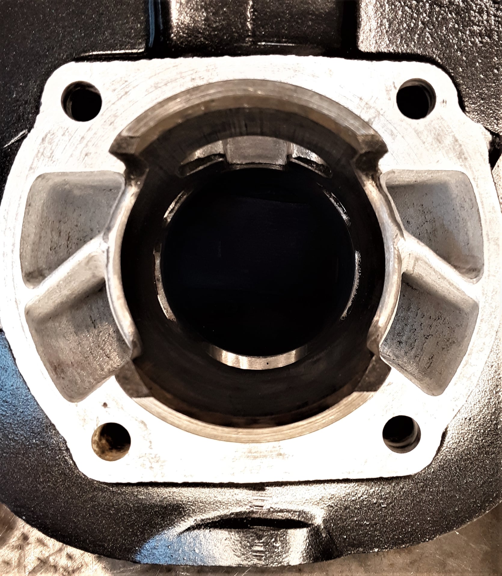
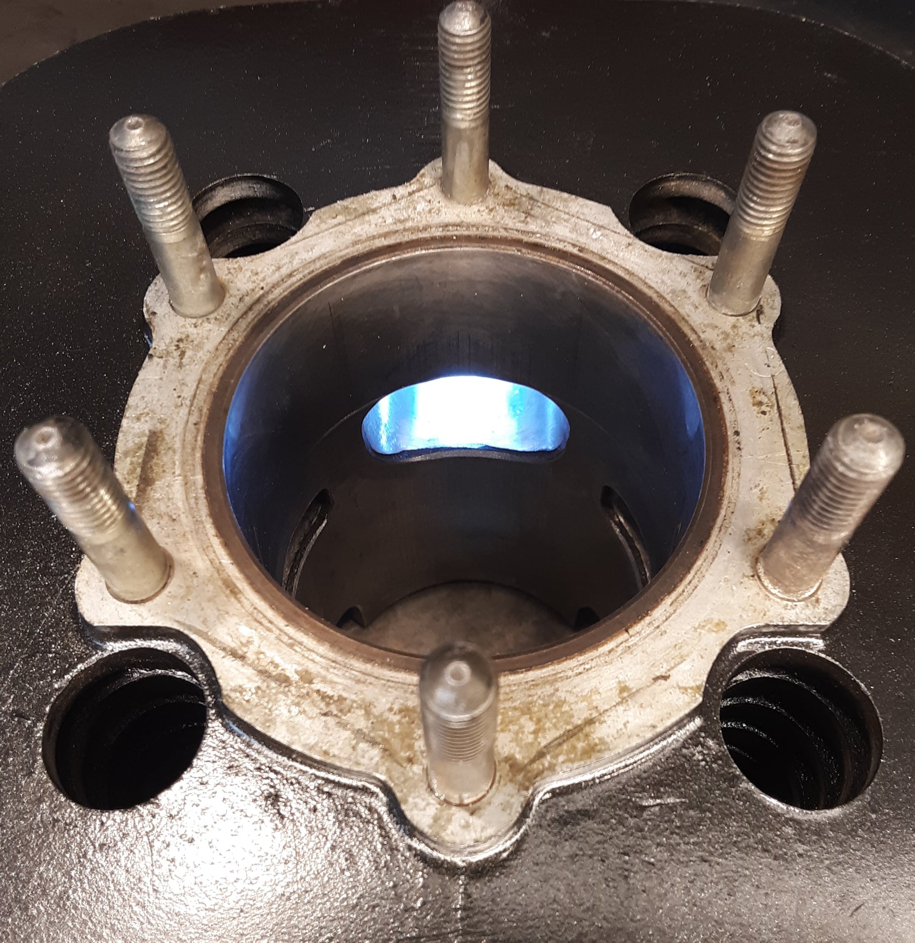
I’m going to ramble on a little about how a two-stroke Trials engine works and how all those holes in the cylinder translate into forward motion. I think I’ll break it down into maybe three posts and try to keep it simple and understandable as possible. Here’s the completed modified cylinder for the 1976 Yamaha TY250 and the partially completed ‘before’ photo. Next will be some flywheel lightening and head re-chambering work I’ll cover in the future.

Let’s talk ‘porting’, that ‘Sorcery’ that is only known to those few Wizard/tuners who have sold their soul to the Devil in order to possess such esoteric and closely-held knowledge.
Actually, a lot of it is simple Science and knowledge of how air (and fuel) flows through an engine during operation. I’ve heard that an engine “Is only just an air pump”, which is a very gross over-simplification that glosses over how intricate all those little passageways work together. We’ll consider the common two-stroke Trials engine rather than the four-stroke, which is a slightly different animal and although it has many more moving parts, is actually much simpler in operation. I’m also keeping to the simple Trials engine as MX, roadrace and shifter karts etc. engines with ‘power valves’ and other such attachments can be much more complicated. Let’s talk about a little history first.
The two-stroke engine started out in life as a dirty, smelly, low power, low-rpm, industrial type engine in the 1870’s and the first truly practical two-stroke motorcycle engine is attributed to Yorkshireman Alfred Angas Scott, who started producing 333cc, 3 HP twin-cylinder water-cooled motorcycles in 1908 (the early 1900’s Scott ‘Flying Squirrel’ is an amazing motorcycle for it’s time and fascinates me to this day as it is the forerunner of the Yamaha RD350LC over half a century later). Contrary to common knowledge, there are several design types of two-stroke engines such as: piston port (early Trials engines), rotary valve (common in roadrace engines), reed valve (later Trials engines), stepped piston, cross-flow scavenging, loop-scavenging and one of my favorites, uniflow scavenging which is a common style of diesel engine used in older large trucks.

The reason the uniflow two-stroke is an old friend of mine is that they use a supercharger to scavenge the cylinder of exhaust gases. In my early drag race days, we used to go to the truck wrecking yards and take off the superchargers to modify and use on our race engines. The superchargers were the familiar GMC roots-type you see on all the old dragsters and came in various sizes according to the volume of air they displaced: 3-71, 6-71, 8-71, 10-71, 12-71 etc. which meant that the volume displaced was designed for a certain displacement type engine, for instance, the 3-71 was for a maximum 3 cylinder engine of not more than 71 cubic inches per cylinder, the 6-71 for a maximum 6 cylinder of not more than 71 CID per cylinder and so on. The other thing about the uniflow two-stroke is that you can win bar bets.
After a couple of drinks, you bet your buddy that a two-stroke uses ‘poppet valves’, the common valves we see in just about all the four-strokes, which, of course, your all-knowing buddy’knows is not true and he will win the bet easily. Then you show him a diagram illustrating the old-style common two-stroke truck diesel with the intake ports around the bottom of the cylinder (controlled by the piston and where the supercharger pumps pressurized air to scavenge the exhaust up and out of the cylinder) and a true poppet valve at the top of the cylinder for the exhaust to exit. These engines used the heat of compression, as diesels do, for air/fuel ignition and a mechanical fuel injection system to get a power stroke each revolution of the crankshaft.
So, you have an idea of where two-strokes came from and I’ll try to get some photos of the cylinder ports in this TY cylinder and then we’ll talk about some of the modifications and how/why they are made. AND, we’ll get into one of the porting designs that made the modern two-stroke come alive, ‘The Schnuerle Loop Principle’, which is the basis of “loop scavenging” and what just about all modern two-strokes use. How exciting! – now you know why I put ‘Gearhead Alert’ on my technical posts.
Jon Stoodley – JSE Trials – Muskogee
Gearhead Alert 007:
Porting Part 3
I doubt that many of you will change the configuration of the ports as it takes special knowledge, experience and tools but I’ll discuss a couple of things I do just for your general knowledge. We’ll get into some things you can do with some easily available tools later on.On this particular air-cooled twin-shock engine.

I’m looking for more low and mid range torque for it’s advanced rider so I’ll start with the exhaust port. In order to make the exhaust make a quicker exit, most porting tech’s raise the top of the port so that it opens sooner and the port is slightly larger and that will work to a degree, it usually is for higher rpm operating engines. However, I’m looking for low-mid “Trials” type power so I don’t want to advance the port timing (which usually decreases the low/mid response) so I widen the top of the port rather than raising it, changing the oval port into a trapezoidal shape, with the wide part at the top. This gives me the extra volume I want without decreasing the length of the power stroke (the pressure on the piston rapidly decreases as soon as the exhaust port opens). In summary, raising the port height moves the power delivery to the upper rpm range and widening the port produces power in a broader range.
In the last diatribe, I blathered on about the “Scneurle Loop Principle” and how the port arrangement promoted “loop scavenging” so in order to further how that works, in this engine I use a “staggered port opening” for the transfer ports.
Usually the top of the 5 transfer ports is the same level but I carve the rear and booster ports so that, when the piston is coming down, the rear, re-angled booster port opens first, then the rear transfer ports open next and the front transfer ports open at the standard time. This starts the “loop” a little early and gets it going in the right direction.Of course, there are a lot of other things I do with the ports but that would be a very, very long discussion and it would be easier to write a book. We’ll talk about one more thing I do with the ports and that is “chamfering”, which is to create a small bevel at the top and bottom of the port to prevent the ring from catching on the sharp edge.
The rings normally “bow” into the port slightly as they pass by and if there wasn’t a bevel there the ring edge would catch the top/bottom of the port and cause damage. Most tech’s just take a rotary tool and a stone bit and bevel the edge, which is fine but it tends to “knock” the ring back in it’s groove abruptly. What I do is take a 15 degree cut on the port edges, wider in the middle and narrowing off to the sides, like a very narrow moon shape.
This will ease the ring back into the groove rather than slamming it back.Let’s talk about some of the things you can do short of having special tools and experience. Matching and smoothing parts where they connect is a good start. For instance, where the header pipe meets the cylinder is often an issue.
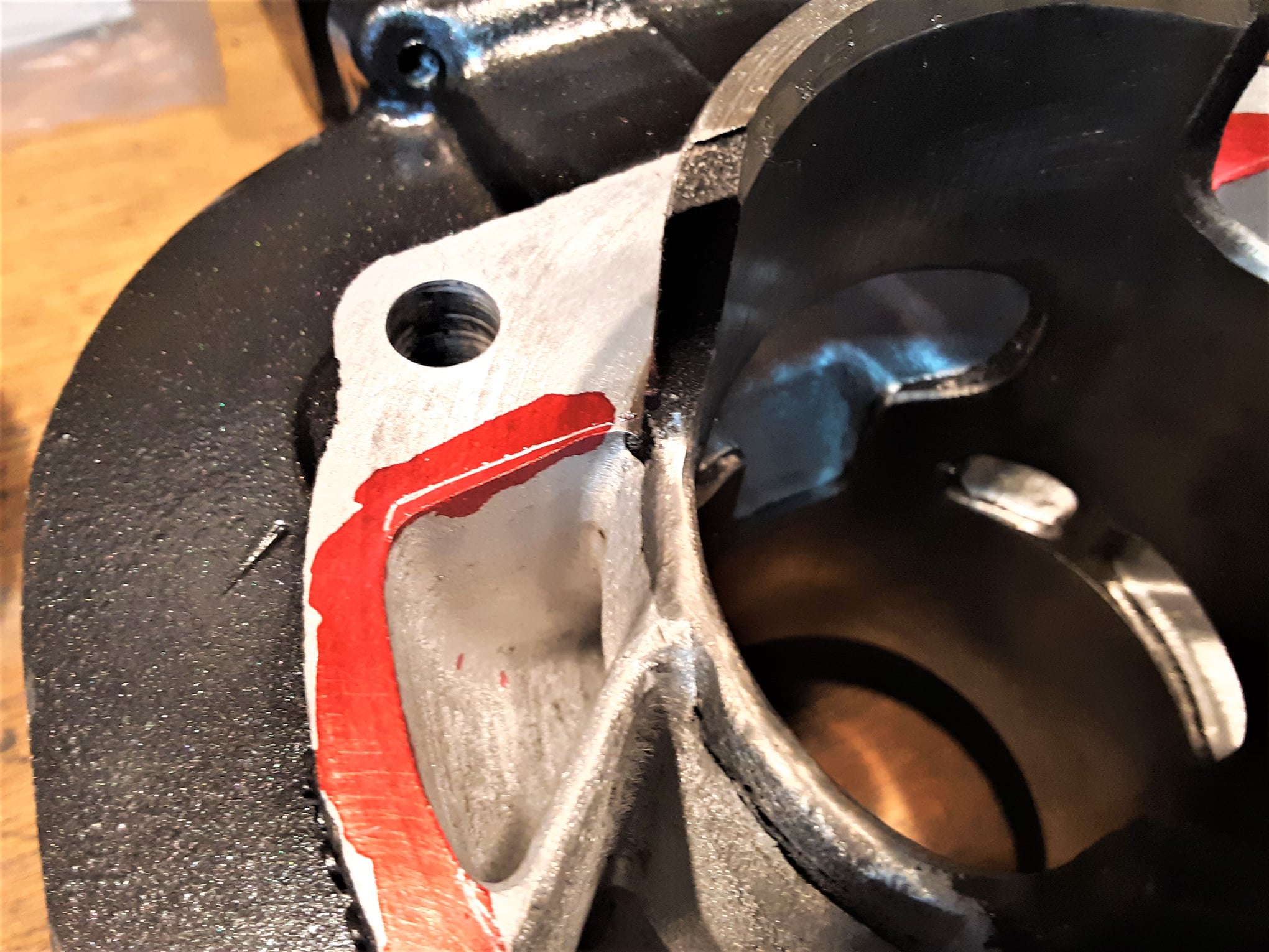
The end of the exhaust port is usually smaller than the opening of the header pipe and a little work with a Dremel type tool and a Carbide bit, followed by some work with a sanding roll can create a smooth transition and a better path for the exhaust gases to exit. You can also polish the port and the inside of the header pipe as this will help reduce carbon buildup.On the intake side, you can match the manifold to the reed cage and the end of the carb spigot to the manifold.
When working on the cylinder, use the base gasket as a template to see if there is any mismatch you can correct. I use a little red machinist’s dye on the parts to make the scribe lines more visible. In the intake ports, you’ll want a textured surface as that actually helps the flow and keeps the fuel in suspension.Now for some tips on working with aluminum. You’ll want to use slow speed and light pressure and take your time. If you turn the bit too fast, the aluminum will actually melt at the cutting surface and clog the bit. If you dip the bit now and then into a cutting wax (or even beeswax) it will keep the bit clean and the aluminum is not prone to clogging it.
I order my porting tools from a company called C.C. Speciality http://www.ccspecialtytool.com/ which has been around for decades and the only company I’m aware of that only carries porting tools.
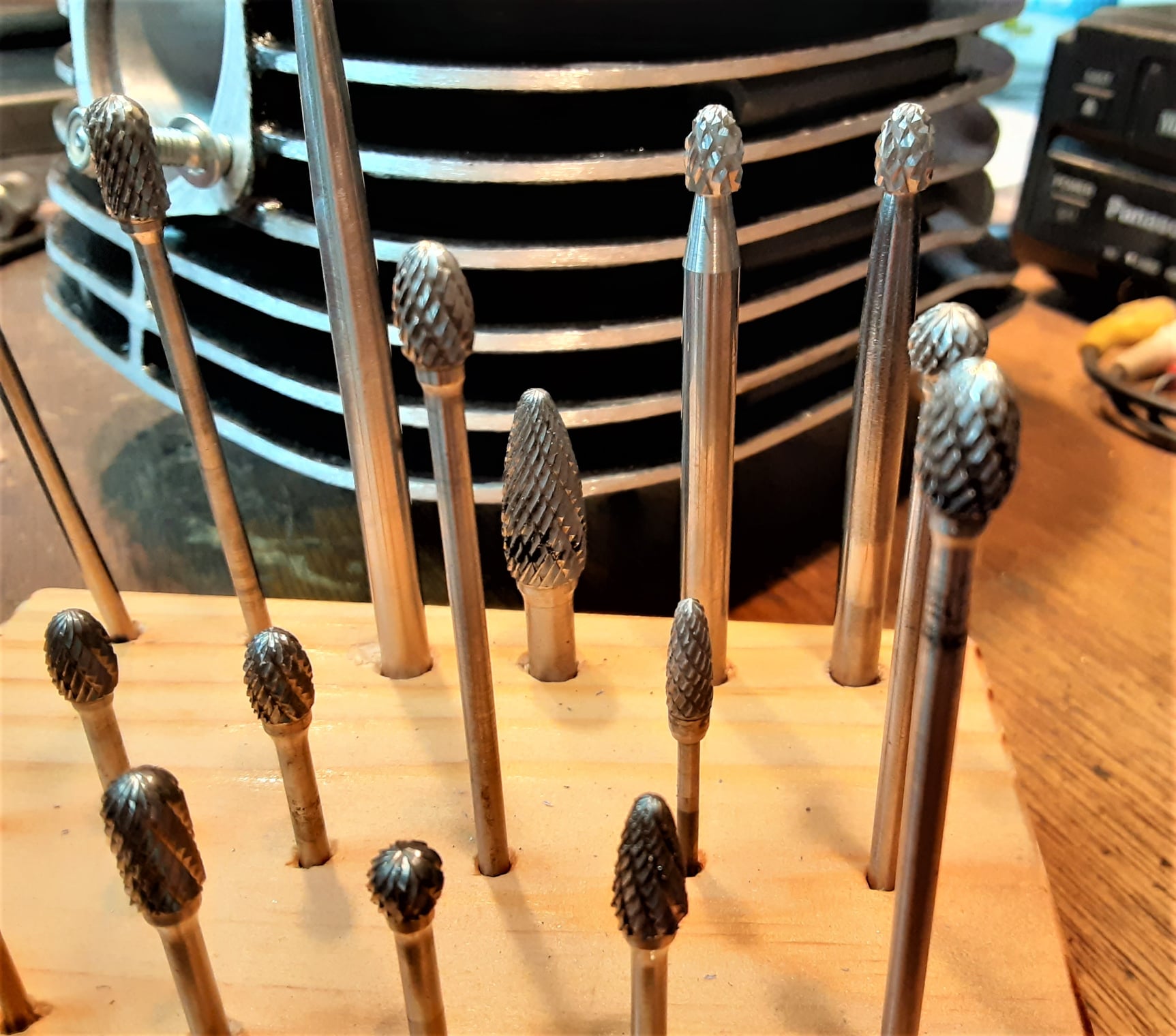
A couple of 1/8th inch carbide burrs (in the “diamond cut” pattern) for your Dremel would work and Harbor Freight Tools carries cone sander kits that will work in a 1/4″ drill. You can always FB Message me if you have questions.
Gearhead Alert 008:
Pistons
This 1976 Yamaha TY250 piston is from a very low hour engine. After measuring piston and bore spec.’s, we are going to re-install the stock piston, but as usual, add a few modifications.
The photos are as follows: Image 1 – just out of the engine.
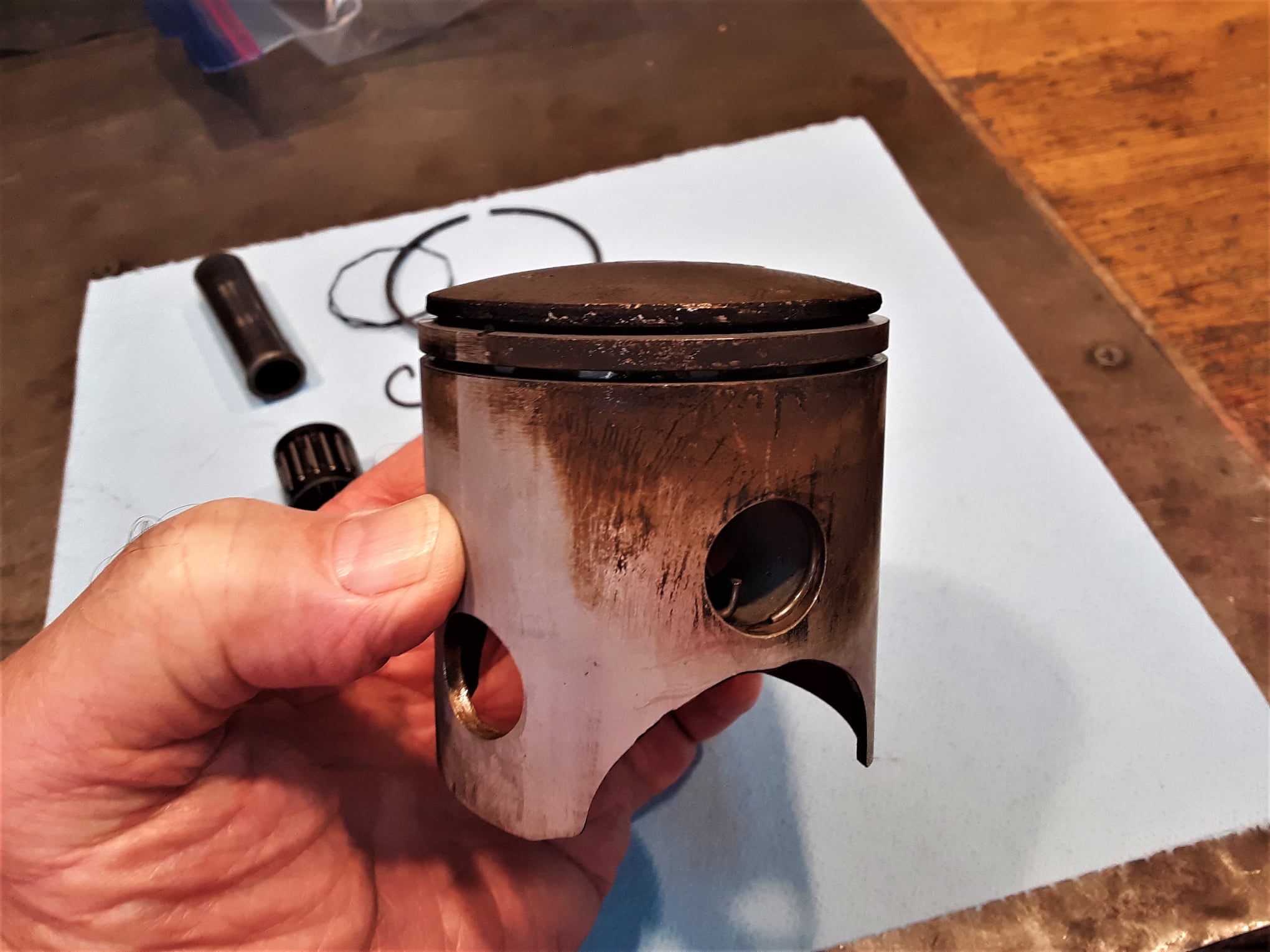
Image 2 – glass bead blasted.
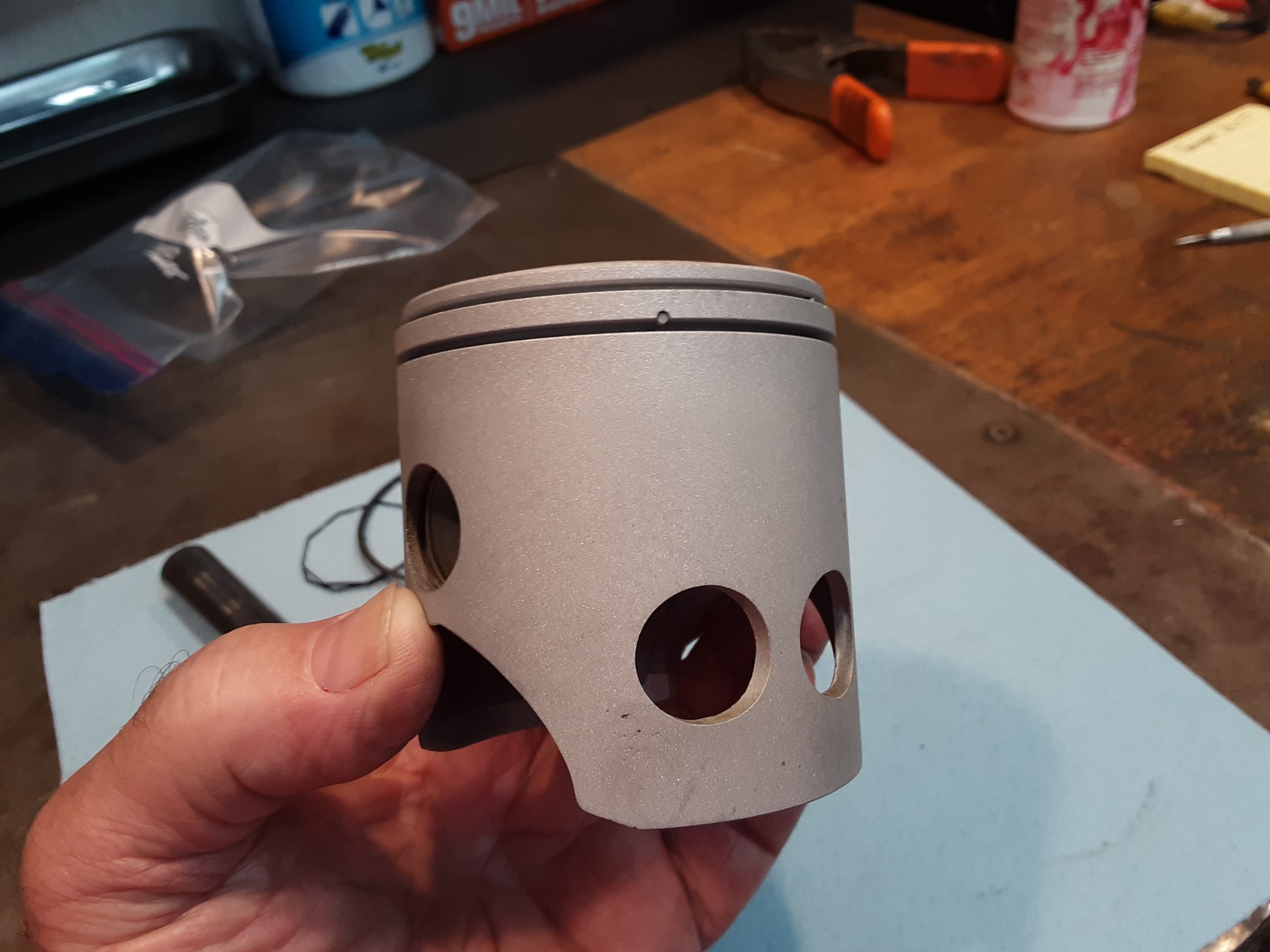
Image 3 – modified.

The bead blasting does a nice job of taking the muck off (this engine ran very rich, so performance was iffy, but it kept a good amount of lubrication available), especially in the small nooks and crannies, without changing the dimensions of the material.
In the modified version, the skirt cutouts have been reshaped and all sharp edges radiused, the piston pin lubrication holes have been enlarged, all the sharp edges of the skirt have been radiused so that they are lubrication spreaders rather than scrapers. Attention was paid to eliminating all ‘stress risers’ where a crack would develop and the skirt was coated with a dry coat of Molybdenum Disulfide (‘MoS2’, operating temperatures -100F to +700F) to reduce friction. If you look at MoS2 very carefully under a microscope, it looks like millions of little, tiny ball bearings and functionally acts the same way to reduce friction. As I’ve said before, details, details, details!
Jon Stoodley – JSE Trials – Muskogee
Gearhead Alert 009:
Two-stroke scavenging
In this alert I’ll try to illustrate how a ‘loop-scavenged’ two-stroke works. This is probably the most common and most familiar two-stroke engine for riders of competition motorcycles and the porting array has been basically the same for many years, mainly because it works so well.
First, some personal background. I was probably less than 9 or 10 years old when I worked on my first two-stroke motorcycle engine, a little cast iron piston/cylinder Villiers that was housed in a Excelsior “Welbike” https://en.wikipedia.org/wiki/Welbike My best friend’s Dad had gone to a war surplus store, when you actually were able to buy real used and surplus military equipment from WWII and bought the little British bike, which didn’t run as you can imagine. I went to the library and got some books on engines, studied them, got some tools from my buddy’s Dad and got it running, to everybody’s amazement, especially mine. My friend and I ran the heck out of that poor little bike and no grassy field or vacant lot in our neighborhood was safe from our onslaught.
It needed constant maintenance and repairing so I learned a lot in the process. After we wore the Welbike out, my buddy’s Dad bought another project for me, a ‘Whizzer’ motorbike (https://en.wikipedia.org/wiki/Whizzer_(motorcycles) that was, what we mechanics call, a ‘basket case’ and this was a REAL basket case as the bike was torn all apart and the parts were, mostly, in three laundry baskets. The mechanical carnage (the parts were just dumped in the baskets with no order), however, did contain ‘The Key To The Magic Kingdom’, that being an illustrated service manual.
I think I memorized that manual from front to back as this type of engine (four-stroke) was new to me. It took me three months of spare time to get the bike assembled and running as my buddy and his Dad were, shall we say, ‘mechanically disadvantaged’ and didn’t have a clue how an engine worked. As a consequence of these two, early childhood projects involving seeing engines from inside-out, I became familiar with both two-stroke and four-stroke engines and am quite comfortable switching from one to the other.
My favorite toy at the time was a small, gas powered, ‘glowplug’ model airplane engine I got for Christmas. I never installed it in a plane but mounted it to a wood box to play with. Model airplane fuel at the time contained castor oil and Nitromethane, so, at a very early age, I got addicted to two and four stroke engines, Castrol-R and Nitromethane, all of which served me well in later years.
In terms of engine porting experience (and how ports actually work), I started at 15 years of age (Lordy, that was about 63 years ago) with my first car, a 1946 Ford powered by a flathead V8. I probably spent more time taking that engine apart and modifying it than I spent driving it on the streets or racing it at the drag strip. I did a lot of work on that engine changing the ports (which were mainly in the engine block) and probably wore out several Carbide bits and 1/4″ drills in the process. Since I’m a very curious person this also tends to make me a good researcher and I spent a lot of time gathering all I could on the subject. In the process I also learned a lot about the science of how ports work and how to use science to make them work better.
So, in this alert we’ll try to draw back the curtain a little and explore how the loop-scavenged two-stroke works in operation. It may get a little confusing if you are not familiar with the basic parts of a two-stroke engine but I’ll try to give a simple version. If you want some basic information, try https://en.wikipedia.org/wiki/Two-stroke_engine, most other sites do not show a loop scavenged engine.Now we’ll look at the engine in operation and in another post, I’ll go into the where, how and why I do some modifications using very special tools you probably do not have, but also some simple things that will make your engine run better that you can do using basic tools, like a common Dremel rotary tool, a small set of bits for carving metal, some small files etc.

In 1926, the German engineer, Adolf Schnürle, developed the system of ports that bears his name and are in wide use today. The idea was to, after the power stroke, efficiently purge the cylinder of exhaust gases in order to make room for the new air/fuel mixture for the piston to compress, ignition to fire and the expanding gases to start the power stroke. His idea was to use a series of ports (in this case, 5) and angle them to face the back of the cylinder so that the new fuel mixture would not get in the way of the exhaust gas flow out of the cylinder.So, lets start on the compression/power phase stroke where the piston comes up and compresses the new air/fuel mixture and just before the piston reaches the very top of the cylinder (‘Top Dead Center’ or ‘TDC’), the ignition fires the sparkplug (it needs to start a little early as the mixture doesn’t ‘explode all at once’ but actually burns quickly out from the point of ignition) and the piston goes past the TDC point and starts down on the ‘power stroke’, exerting pressure on the crank due to the expanding gases from the burning air/fuel mixture. I’ll cover what happens in the combustion chamber during ignition in a later post about head modifications. OK, so now we’ve talked about roughly 1/2 of the two-stroke engine’s crank revolution and as the two-stroke goes through all the intake/power/exhaust stuff in one crank revolution, we are half the way there, right?
However……as the T.V. salesman loudly exclaims when pitching his product, “But wait! There’s more!!!!) and here’s where things get busy….very…very…busy.
So now we are finishing the power stroke as the piston descends and the top of the piston ( called the “crown”, or in the case of ‘Dykes’ rings, the top of the ‘L’ shaped ring) meets the top of the exhaust port and starts to open it as it slides past. This allows the cylinder to evacuate spent gases and relieve pressure in the cylinder to allow the fresh air/fuel mix to enter when the piston crown starts to open the ‘transfer’ (intake) ports. The time from when the exhaust port opens and when the transfer ports start to open is called ‘Blow-down Time’, where you try to get as much exhaust gases out as you can and drop the pressure in the cylinder so when the the transfer ports open, the air/fuel mixture does not have to push against it.
Here’s where we run into a big dilemma. We’ve got this pressurized tube (engine cylinder) with a big hole in the side (exhaust port) that is spewing hot air (exhaust gases) and down lower we are starting to open a bunch of more holes (5 intake ports) to spray a pressurized air/fuel mixture into the tube. How do we keep the two different mixtures apart and not allow the new air/fuel mix to just go out the exhaust port as when the piston reaches the bottom of the tube (Bottom Dead Center or ‘BDC’) all the ports are wide open?
Here’s what Schneurle did. He put the two front transfer ports fairly close to the exhaust port and aimed them low and directly to the back of the cylinder, which kept the intake mass mostly out of the way of the exiting exhaust mass. He then put another two transfer ports roughly on either side of the cylinder and aimed them towards the back and with slightly more of an upward angle. The next and last port was directly at the back and was aimed steeply upward toward the sparkplug.Try to picture this: the piston is moving down in the cylinder on the power stroke and the exhaust port opens and the exhaust gases are rushing out. After a short distance, the piston starts to open the intake ports (while the exhaust is still exiting) and instead of just plopping their load of fresh air/fuel mix into the middle of the cylinder, they spray it to the back wall and up the wall towards the sparkplug, creating, in effect, a ‘loop’ of air/fuel mass traveling up, over and down, helping push out the spent exhaust gases.
So, I know it’s complicated, especially if you are not familiar with the insides of a two-stroke motorcycle engine, but I hope this gives an idea, and takes some of the mystery out of what all those holes do in your engine’s cylinder.
In discussions, I’ve often said that although a two-stroke is much more simple in construction than a four-stroke engine, in operation, it is much more complex. So, in the next post on this subject we’ll get into the nitty gritty of the where, why and how we carve up those holes to help make the engine more efficient and better suited to the task.
Jon Stoodley – JSE Trials – Muskogee
Gearhead Alert 010:
Drain Plugs and sealing washers
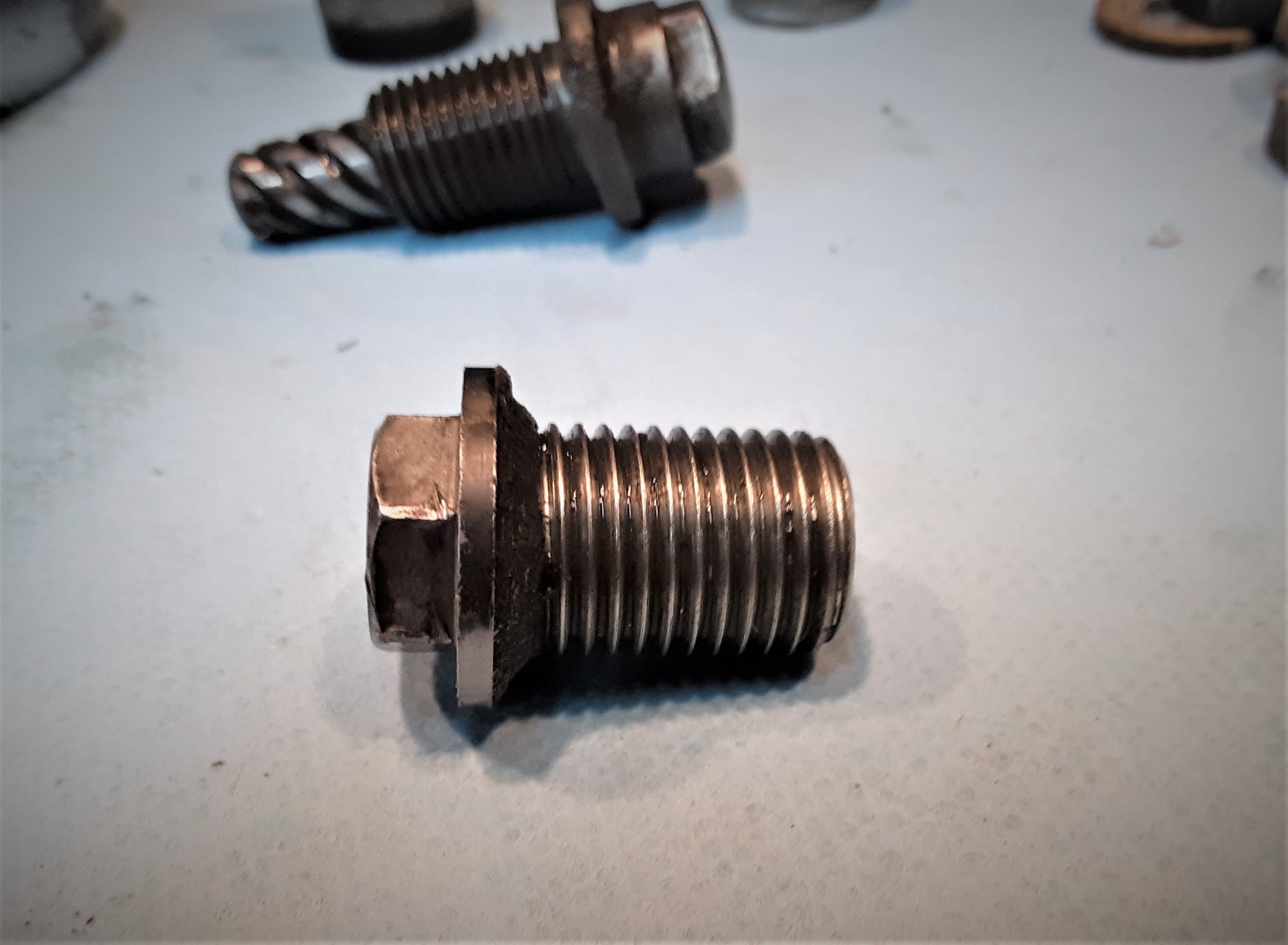
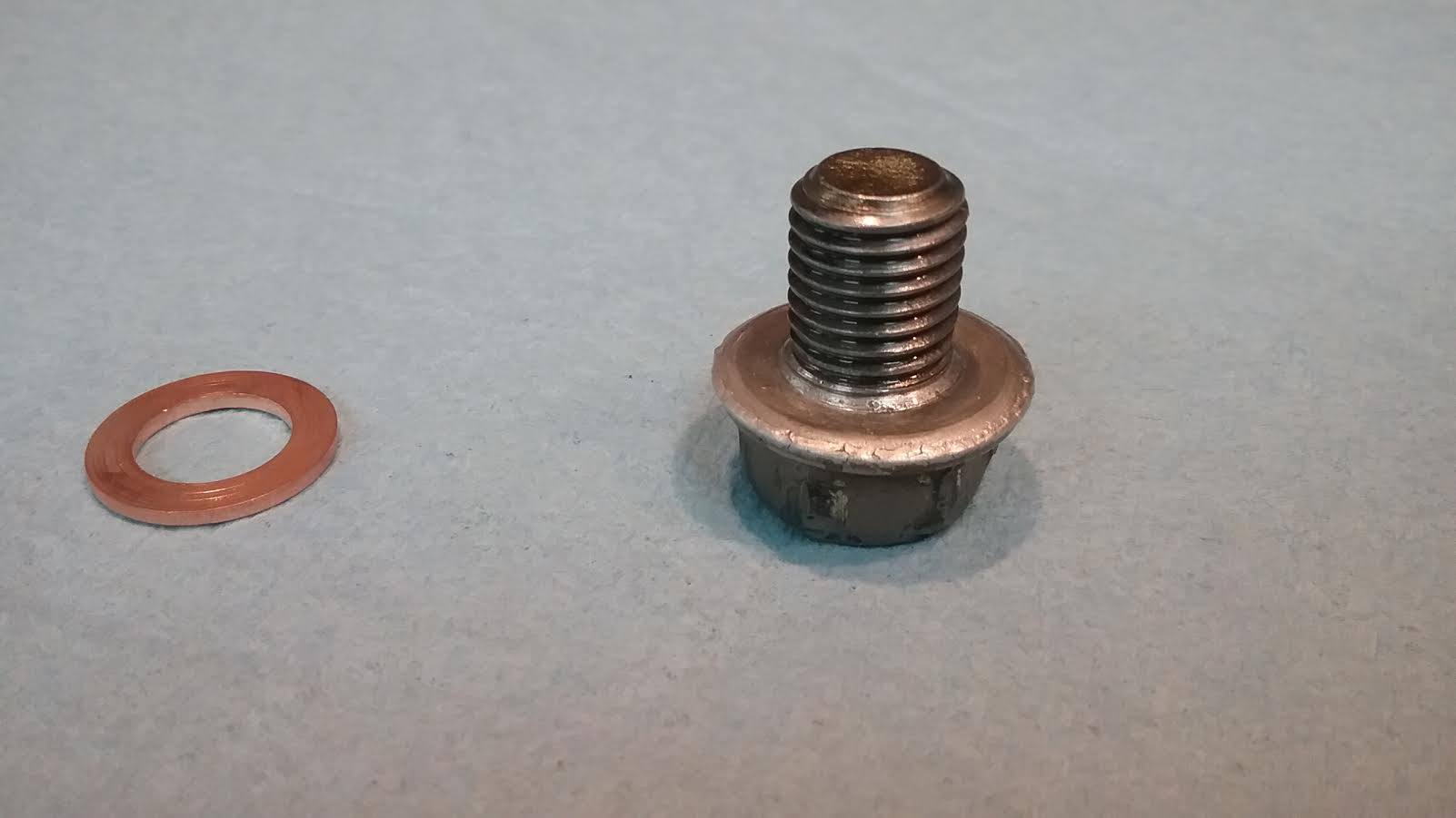
This is a drain plug from a 1976 Yamaha TY250 and when I removed the case drain plug it reminded me a problem that can occur.
You’ll notice the fiber washer has worn away except for the beveled part left at the bottom of the threads. That is because the remaining part assumed the bevel shape machined into the top of the plug hole in the engine case (‘countersunk’ if you will). This is generally not a problem with fiber washers, but with aluminum and rarely brass/copper washers, this can be a VERY expensive problem and that problem is cracking the engine case.
I first saw this issue come up with the early Honda MX engines with the factory aluminum washers (and some other engines with the beveled drain hole in the case) where there would be a fairly wide crack in the case coming out from the hole resulting in constant oil loss. Riders, of course, blamed Honda for poor materials but the first time I saw it, the cause was obvious.
What happens with aluminum drain plug washers is that each time you tighten the plug, the soft aluminum will compress a bit and the inside of the washer will be forced down into that countersunk area, gradually forming a wedge shape like the fiber left on this plug.
When the washer gets thin and the countersunk area is essentially filled with aluminum, when the plug is again tightened, compressing the washer further, it will cause the wedge to exert great pressure outward around the hole and eventually split the case. Repair or replacement is expensive and new engine cases are almost always sold in matching machined pairs.
The moral of this story is that aluminum drainplug washers have a very short service cycle on engines with countersunk drain holes (most engines) and I wouldn’t use them more than a couple times (I would replace them each time on my engines). Less soft brass and copper washers should be inspected carefully each time they are removed and if there is any sign of a wedge starting to form, replace them.Here’s a photo of a CR250 drainplug I found that had the aluminum washer used too many times and you can see the ‘wedge’ at the bottom of the threads and yes, this plug split the cases in that engine.
Jon Stoodley – JSE Trials – Muskogee
Gearhead Alert 011:
Squish Bands
Oh goodie! we’re going to talk about two-stroke stuff again, specifically ‘squish band’ clearance and configuration. Four-strokes also have ‘squish but it’s usually referred to by the 4T guys as ‘quench’ and can be more complicated due to the variations of most 4T chambers and valves entering into the equation but the concept is basically the same.
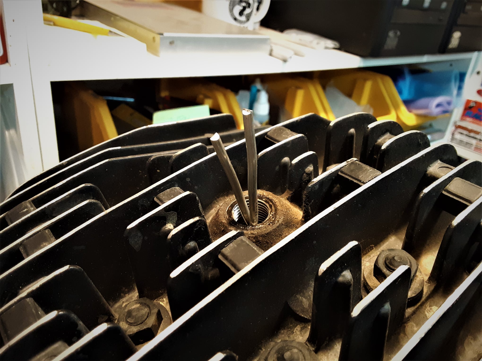
When disassembling an engine for modification, the first thing I do is to measure the squish band clearance using two pieces of solder (with both tips contacting the cylinder wall). The reason I use two (one in front and one in back) and not the normal one piece of solder is that I want to be as accurate as possible.

The two pieces compensate for ‘piston rock’, or the piston tilting slightly in the bore by the solder pushing on just one side and the solder pieces load both the front and rear at the same time.

The two piece system also will give me any variation in the clearance from front to back. You can see by the figures that the clearances are slightly different from front to back, but not unusual for a production engine due to machining tolerances.
The solder will also tell me if the angle of the band and the angle of the piston crown are different (the ‘taper’ measurement), which in this case is also true. The difference in these angles and the squish band clearance will have an effect on the ‘MSV’ or Maximum Squish Velocity value and affects performance. I won’t go into MSV as it will bore you to tears and make your eyes glaze over. You know, that look I get when a poor rider comes up to me at an event and asks a technical question, just expecting a simple yes or no answer and I start blathering on about Physics, mathematics, probabilities and a bunch of other inane things and I remember to stop myself and ask: “Oh, I’m sorry! Do you really want to know all stuff or just the simple answer?”
They usually want the simple answer. When I get cranked up, I’m difficult to slow down!
What all this means is, from the measurements, that I will want to completely machine all new surfaces in this head to bring them into the proper relationships.
Jon Stoodley – JSE Trials – Muskogee
Gearhead Alert 012:
Gas Gas 2002 – Pro Clutch
OK, let’s talk clutches. Not a high-excitement subject, but in my experience, Trials riders rely more on their clutches during competitive events than any other form of motorcycle sports. A lot of questions I get from around the world relate to clutch problems or asking for techniques on how to improve them. In this article I’ll delve into the Gas-Gas Pro clutch as it is unique among motorcycle clutches, but I’ll also cover some tips relating to clutches in general.
Simply put, a clutch is what transfers and modulates power from the engine to the transmission, which in turn then transfers it to the chain and on to the back wheel. If you don’t know where your clutch is located in your engine, you probably shouldn’t be working on it without some experienced guidance, as they can be somewhat tricky to service properly. The easiest way to work on the clutch, in most cases, is to lay the bike on the ground (the left side on the Gas-Gas Pro, for instance) and this will keep the transmission fluid from draining, but make sure there are no fuel leaks (I like to remove the fuel tank, which only takes a couple of seconds). On the Pro, to take the sidecase off to get at the clutch, you can take the three bolts out of the Waterpump and twist it slightly to disconnect it from the case. It can be ziptyed to the front frame downtube, out of the way, so you don’t need to drain the coolant. After the sidecase is off, you can ziptye it out of the way so you don’t have to remove the hydraulic line.
Spend a little time looking at the clutch as it is different from all the others, and you want to have an idea of how it will go back together. In order to keep the hub from turning when removing the screws, stuff a clean cloth shop rag in between the clutch hub gear and the crankshaft gear (or ‘primary gear’, as it is also called).
Loosen each of the ten small bolts a little at a time on opposite sides to maintain an even pressure release, something you will always want to do with any component that has more than one fastener, such as cylinder heads, sidecovers etc.
The 2002, first year Pro uses 3mm socket buttonhead screws that can be hard to remove. You’ll want to replace them with the 03’ up 7mm head 12-point screws. A trick to removing them is to use a T-15 Torx bit as an “ez-out”. Just tap the Torx bit into the hole, which will break the bond, and back the screw out. You’ll want to replace the screws with the updated ones, but if need be, you also can re-install the old style screw with the Torx.
Incidentally, a T-45 Torx will work the same way on stripped oil drain plugs on the Gas-Gas, usually caused by over-tightening them with a worn Allen wrench (dress the ends of your non-ball end Allen wrenches now and then to keep the gripping edges sharp). I carry a full set of Torx bits in my toolbox as they make great tools to remove stripped Allen bolts/screws. Keep track of how parts come off by laying them, in sequence, on a long paper shop towel.
You’ll notice the clutch has only one ‘spring’; actually a large coned washer called a Bellville spring, and three fiber plates. Inspect all the parts for unusual wear or damage.
A digital caliper works best to inspect the two critical measurements in the Pro clutch. One is the clutch pack and the other is the ‘finger’ height above the center of the hub. The standard measurement for the clutch pack (the thickness of the fiber and steel plates combined) is 9.75mm, plus or minus 0.1mm.
A used clutch will generally be, due to normal wear, a little thinner than that, which is not necessarily bad, except when it adversely affects the other critical measurement, which is the height of the fingers (those triangular shaped metal plates surrounding the center of the clutch). The height of those fingers above the inside of the hub (just next to the center hole) can range from a minimum of 16mm to a maximum of 19.5mm (17mm is good).
Another feature of the Pro clutch is its adjustability. With the fingers set low (16mm height) lever pressure will be slightly higher and the clutch will engage quicker. If you like an easy pressure on the lever and a more progressive engagement like I do, set the fingers higher. I like mine set at about 18mm.
As mentioned before, the height of the fingers is dependent on the thickness of the clutch pack. The thickness of the clutch pack is adjusted by substituting steel plates (non-fiber) of three different thickness. The plates come in 1.5mm, 1.4mm and 1.3mm, all interchangeable. The thicker the clutch pack, the lower the fingers will stand out from the center hub.
I’ve found that due to the variable mechanical leverage dependent upon position on finger contact, the ratio of change in the clutch pack thickness to finger height rises at a slightly exponential rate, which translates to “Yea, cut and try seems to work best”. I’ll use a plate that is only 0.1mm different from what I have in the pack, assemble the clutch and hold it together with three screws around the hub and measure the finger height, repeating the process until the finger height is exactly where I want it.
Once set, without unusual wear, the setting will last a long time.
One of the things I do for a very light, smooth lever pull is to polish the inside of the “top hat” or servo cylinder (that thingy that looks like President Lincoln’s old stovepipe hat and presses on the fingers to release the clutch). I use ultra-fine Cratex rubberized abrasive bits that you can find in any good industrial supply shop. You just want to make the surface finely polished but not to remove any excess material. This will reduce the “stiction” of the seal and/or o-rings against the cylinder bore. When re-assembling the sidecase, be sure to align the slots on the crank gear that drives the water pump with the lower bolt hole and then align the pin on the water pump drive with the same hole so the pump will slide in without damage. The longest bolt on the water pump housing goes at the bottom. Also, be sure to align the kickstart spring loop to fit in the machined hole in the sidecover.
For the Pro clutch, the factory recommends 5W-30 automotive oil, which works well. Some riders use Dextron III or the higher temperature tolerant Ford Type-F ATF. I use General Motors AutoTrac II transfer case fluid, which I get at the local GM parts counter. I’ve had excellent results with it and it may be why my Pro has the original 02’ clutch it came with.
Another factor is that I like to change it about every 10 to 20 hours of use, especially since the transmission fluid also lubricates the crank main bearings and I want to make sure it stays clean.In terms of regular clutches, there are a few points I’d like to cover that may help. Make sure there always is a little clearance between the lever adjusting screw and the plunger that presses in on the master cylinder piston, otherwise the system will not be able to self-adjust and it will cause drag and make you think there is air in the lines. Also check to be sure the piston is returning back completely to it’s stop at the circlip (and when pressed in, exerts a little resistance), and if not, you’ll want to replace the piston return spring inside the master cylinder. If the boot that the plunger goes through is torn or not seating in it’s groove, I’d get a new one as that area is where a lot of moisture and dirt enter the master cylinder and can cause damage. If you can’t buy the boot just by itself, I’d opt for the repair kit that includes it, as I think this is an important component to keep in good shape or it will fail you at the worst possible time.

Sometimes the steel plates in the clutch pack will become glazed and cause chatter or slipping. I think the best way to de-glaze them is to use a surface plate and some 180 or 240 grit wet/dry sandpaper and a little water (which will hold the sandpaper down on the plate).
Not wanting to have a massive granite surface plate that literally weighs a ton take up space in my small shop, I mounted a 20 inch square, tempered, thick piece of glass I had made for me at a glass shop (they rounded the sharp edges) to a piece of ¾ inch plywood, and it works very well. Put a little water on the glass and then the sandpaper, which will be held down by surface tension.
Add a little water to the grit side of the sandpaper and then, using a figure “8” pattern, rub the plate to deglaze it. You can also use the glass to check the plate for warpage, just put the steel plate on the glass and check with a thin feeler gauge for a side that stands up off the glass surface, indicating a warped plate.
Check the steel plate carefully and most likely it is a stamped piece that will have a sharp side and a radiused side, caused by the stamping process.
When assembling the clutch, put the radiused side in towards the engine, which will help the engagement to be smooth. The splines on the inner hub can be polished with Cratex to allow the plates to slide easier.
Check the outer hub inside the “fingers” that the tabs of the fiber plates rest and if there are deep grooves, replace the outer hub (or the clutch “basket”, as it’s called). What happens when there are grooves on the sides of the fingers is that the fiber plates try to self-center in the groove, rather than slide smoothly when the clutch pack is compressed upon release of the clutch lever. You could try to file those grooves down, but you’ll just end up with a sloppy action clutch and greatly increase the possibility of one of those fingers breaking off and causing severe engine damage.
If your clutch is slipping and you just gotta ride and your dealer is out of springs, a stop-gap measure is to add a little preload on the springs by adding a washer at the bottom of the hole where the spring goes. Sometimes spark plug washers are the right size, but this is only a temporary fix and the springs (and more than likely the fiber plates) will need to be replaced as soon as possible.
Jon Stoodley – JSE Trials – Muskogee
Gearhead Alert 013:
2002 Gas Gas Pro Set-Up Tips
The 2002 Gas Gas Pro 280 was generally considered a slightly ‘hyper’ engine and a little too much for the average rider to control easily. Since I have a fairly good idea of how to modify engines, I always adapt the motorcycle to me rather than have to try to adapt to the motorcycle.
My 280 is quite easy to ride and lugs down to walking speed without missing a beat. I like a good, smooth low-RPM response and a healthy mid-range.
Riders will often complain that they need more top-end power but in reality, they spend very little time at full throttle. Low and mid range power delivery is where most of the work is done and where most riders spend their time.
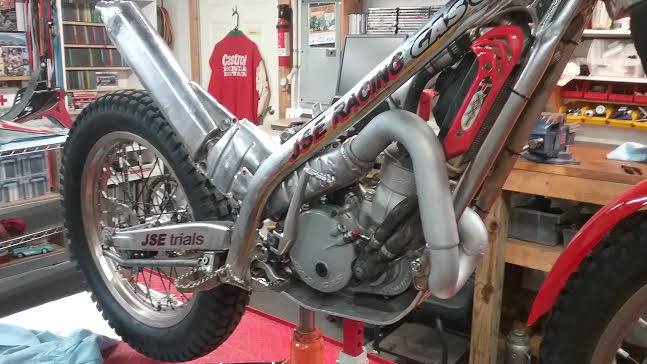
I’ll touch on just a few of the modifications on my bike that have worked well for me. The 02′ Pro came with a steel mid-muffler that weighed a LOT and clogged up over time. I modified a later model aluminum muffler for my bike but the obvious thing different here is the head pipe I designed and fabricated. It is longer with a different transition in diameter and actually tucks in much better than the stock one.
I run a carbon fiber heat shield on it to keep from burning my riding pants, which I recommend. I make sure the mufflers are packed correctly as it has a direct effect of performance.I run an Amal all aluminum throttle, which is slightly ‘slower’ than the white tube Domino and much more durable than the plastic housings on the Domino. Boyesen dual-stage reeds, along with some minor cleaning up of the intake/reedcage areas, smooth out the throttle response and according to flow bench tests I’ve run in the past, the Boyesens flow better at higher RPMs than the stock single stage.
Without question, of course, I’ve taken the time to correct my jetting, which is different than stock recommendations due to the modifications.Since the static ignition timing on the Pros is non-adjustable (notice I said ‘static’, not switched dynamic-mapping [which does not change the static timimg anyway] and yes, static timing can be ‘adjusted’ by slotting the mounts for the CDI Hall sensor, but I won’t get into that) I went about the issue in a different way by running high-octane race fuel (down here in the ‘flat lands’, however up at the Ute Cup’s high altitude I run locally sourced pump fuel for other technical reasons I won’t go into).
High-octane race fuel burns at a slower rate, which is how it resists detonation. In addition to other qualities, it lowers the “IMEP”, which stands for Indicated Mean Effective Pressure, or more simply, the average pressure acting on a piston during the different portions of its cycle.
Lowering the IMEP reduces the combustion pressure at TDC on the compression stroke, the same as slightly retarding the static timing. If you want to soften the off-idle throttle response a little, try running high-octane race fuel to see if it gives you the results you are looking for.
Jon Stoodley – JSE Trials – Muskogee
Gearhead Alert 014:
Lubrication
THE DYNAMICS OF FLUIDS – By Jon Stoodley
When I was a kid building bikes and cars, knowing what kind of “fluids” to be used in them was a pretty simple process, 30-weight oil in the engines and regular old brake fluid in the brake system. Coolant for cars (bikes were air cooled and if you wanted a “dirt bike”, you learned to build one from a street model) was usually plain water and if you lived in a cold climate, anti-freeze was added. That was it.
Well, Fuel was also a fairly simple decision; whatever was the cheapest, except if you had hotrods like I did and then you would opt for that really expensive stuff: Chevron Supreme out of the corner gas station pump at 102 Octane and costing dearly at 29 cents a gallon. Nowadays, with the high-tech machinery we have as vehicles, we have a wide variety of specialized fluids and lubricants for our cars and it can be a little confusing, so a lot of us take our vehicles in for service. On the other hand, as Trials riders, servicing our bikes is considered to be part of the Sport and we think nothing of doing our own work. For us “Old Hands”, we usually have a certain amount of experience to draw from (some of it derived from some very expensive mistakes) and we have a fairly good idea of what type of fluid/lubricant works well in what type of part. For a “new-to-the-Sport” Trials rider, however, this subject can be wrapped in total darkness.
Consider the fact that we use fluids of various design parameters in brake hydraulic systems, clutch systems (that have different requirements from brakes), fuel/premix, transmission/clutches, forks, shocks etc. And this list does not include the various service lubricants we use with chains, bushings, bearings, levers, throttles etc. In my years of racing, I’ve had the privilege to associate with a very knowledgeable, and better yet, helpful, group of Chemists and Engineers who shared my love of competition machinery and were delighted to trade information from their area of expertise for information from my area of expertise, a partnership designed to be, pardon the pun, a “win-win” situation. What I’ll try to do is to touch on a few tidbits concerning operating fluids and lubricants that have worked for me and, as I’ve found that most riders have access to the Internet, point out a few websites I’ve found useful. The Internet is a wonderful, expansive source of research material and useful information; unfortunately, some of it lacks intrinsic veracity (one of my old University terms that essentially means; “ rises in truth to about the level of dog poop”) so we owe it to ourselves to be good “consumers of information” when using the Net and check out what seems suspect. If you have an Owner’s Manual or Service Manual for your bike, be sure to spend some quality time with it. It will save you many mistakes (and possibly a lot of money too) and usually will tell you the specific fluids and lubricants that work well on your particular bike. For a question that may be particular to your brand of bike, I wouldn’t hesitate to contact your local dealer or even the brand importer. From my experience, they will bend over backwards to make sure you have a positive experience with their bikes and provide the support you need to do it. In no way can I over-emphasize the important nature of regular maintenance, which includes fluid changes. A lot of the problems I see happen can be directly traced to poor maintenance. Trials bikes are designed for full-on competition use, which places a greater degree of stress on the parts, so it makes sense to treat them more like a thoroughbred than a mutt. Probably the best format to deal with information like this is to take each component of the bike and explore the fluid/lubricant properties that seem to best fulfill the component’s requirements.
FORK OIL – Fork oil needs to do several things; for one, it helps provides the damping necessary to prevent the front end of the bike from bouncing around uncontrollably like a pogo stick, and it does this, in part, due to the viscosity, or “thickness” of the fluid. Fork oil viscosity can be measured using different tests and the results may be expressed in units denoting “SUS” or “Saybolt Universal Seconds”, “VI” or “Viscosity Index” or “SAE” for “Society of Automotive Engineers”. Most of the time riders generally go by the SAE rating or “weight”. SAE 10 weight fork oil could also have an SUS rating of 165 and a VI rating of 150, for example. Most newer forks that use internal cartridges take a lighter oil such as a 5 weight and older forks that use a different mechanism for damping (called a damper rod) use a heavier weight oil such as 15 or 20 weight. Often you will see two numbers together by the SAE weight number, such as “85-150” by the “SAE-5 wt” and this is the SUS and VI numbers of that fork oil. Unless you are into high-performance, severe-use suspension modifications, the SUS and VI rating spec.’s will not be as important to you and the SAE rating will be what you are looking for.Sometimes, if the oil meets several of the SAE temperature/viscosity criteria, it will be expressed as a “range”, and you’ll see the markings indicating a “multi-grade”, like the common “10W-30” in motor oil. It does not mean the oil “changes viscosity”, but that it resists viscosity changes over the range of the temperatures tested. Temperature and viscosity are closely interrelated in oils and the “W” on the multi-grade oils, like “10W-30” refers to the cooler temperature range (“W” for “Winter”) that the oil is suited for (the oil’s viscosity equivalent in cold temperatures). The other thing a fork oil must do is to lubricate the internals of the fork such as the springs rubbing against the inside of the tubes, the Teflon bushings that allow the tubes to slide smoothly inside each other and the various bushings inside the cartridge. As such, you will want to change the fluid on a regular basis to keep everything in good shape. I like to change mine about every 6 months. When you clean out the lower fork tube, you will find a fine metallic grunge in the bottom of the tube, which is one of the contaminates that can affect damping, and those are the particles that have rubbed off the outside of the springs (which is why the springs will show a polished line on the outside of the coil). Riders will often diagnose this as dirt getting into the fork somehow, but this is not the case.Forks need oil that is specifically designed for use in them; any old oil will not work as well. There are usually special additives for friction reduction and anti-aeration. The anti-aeration additives help the oil to not retain very small air bubbles (foam), which will quickly degrade damping properties.Here are a couple of interesting sites.http://www.peterverdonedesigns.com/lowspeed.htmhttp://www.sportrider.com/…/146_0006_susp_lingo/index.html
SHOCK OIL – Unless you are a hard-core gearhead like me and have the experience and tools to service shocks, you will probably not (and probably should not) mess with the rear shock. They are Nitrogen charged to a fairly high pressure and will take a different oil depending on, for instance, if the shock body is steel, anodized aluminum or non-anodized. If you do have a rebuildable shock (a lot of the bikes do not have rebuildable shocks) you will want to have it serviced now and then. I service the rebuildable shocks on my bikes about every 8-12 months, depending on the severity of use.
CLUTCH HYDRAULIC FLUID – This is an area where I deal with a lot of questions from the websites I’m on. Your bike will use one of three classifications of fluid for the clutch, DOT-3/4/5.1, DOT-5, and mineral oil. DOT-3/4/5.1 are glycol based, DOT-5 is a Silicone based fluid and mineral oil is what it sounds like, but it is a special low-viscosity, light mineral oil just for clutch systems. You can’t use the stuff you buy from the corner drug store. The three types of clutch fluids DO NOT mix with each other, so you must be very sure what type of fluid you have in your system before adding any extra. Clutch systems that use mineral oil usually have a green cover on the master cylinder as well as a warning as to what type of fluid is installed to avoid mistakes.If you change fluid types, say from DOT-3 or mineral oil to DOT-5, like I do with my clutch systems, or mineral oil to DOT-3/4/5.1 glycol type (which you probably would not want to do), you must completely take apart and flush out the system, including the master cylinder and servo cylinder. You can’t just drain the system and add the new type of fluid; the residual fluid left in the system will not mix with the new type. Another problem that may arise is that the seal and o-ring material is different for mineral oil and glycol fluids. Glycol fluids will attack mineral oil seals/o-rings, so you must also install DOT-3 compatible parts if you are making that kind of switch. If you are changing over to DOT-5 (Silicone) from the glycol or mineral oil fluids, not to worry, the DOT-5 is essentially chemically inert and can be used with both types of seals/o-rings from my experience. I like the DOT-5 (Silicone) fluid in my clutch as it is very slightly compressible (but because of this, it is not as good for brake systems as it makes them feel a little “spongy”) and makes the lever modulation smoother, will not attack the rubber boot on the master cylinder and seems to have good lubricity which also helps smooth out the clutch take-up. There are a lot of brands of glycol brake fluids that have the temperature tolerance as part of the name, like “BlaBla/600” or “Stopfast/570” etc, but you will probably only be concerned with the DOT-3/4/5.1 designation on the container and usually plain old DOT-3 is fine in the clutch as the glycol using system for clutches is not subject to the high temperatures of the braking systems.
BRAKE HYDRAULIC FLUID – You would think that brake fluids would be a much more complex issue than clutch system fluids, but I’ve found the opposite to generally be true as far as Trials is concerned. If you were running a roadracer or another type of vehicle that placed a high degree of stress on the braking system, this would be a difficult decision that you would carefully consider, but Trials riding is probably easier on brakes than most other forms of motorcycle sports (except maybe hill-climbing and oval-track flat tracking bikes, which essentially do not use the brakes). A good quality DOT-4 brake fluid will probably meet the needs of most Trials riders. Just about all the braking problems I’ve seen on Trials bikes are not specifically fluid related, but a result of mechanical condition or improper maintenance. Always clean the master cylinder cap before taking it off to avoid dirt in the system, which will damage o-rings and seals. Change fluid once a year if you can, as clean, uncontaminated fluid is what the brake system needs in order to do its job. Avoid old, opened containers of brake fluid when servicing your brakes as you’ll probably be just putting water contaminated fluid back in. Slightly overfill the front brake master cylinder so that when you put the bladder/cap back on, a little bit will spill over. This will reduce the amount of air under the bladder. Rear fluid reservoirs are often non-vented; so only fill them up to about 2/3rds full. NEVER put mineral oil in a brake system, it only works in the clutch system and can create serious braking problems (as in “NO BRAKES!” being shouted out a lot).Brake fluid has to be able to absorb a little water but must not have an unusual affinity to do so. This is why the glycol-base fluids have both a “dry” and “wet” boiling point number on the container. The “dry” boiling point is for new, uncontaminated fluid and, as I remember, the “wet” boiling point is with a 3.7% saturation of water, which, as water boils at 212 degrees normally, will affect the brake fluid boiling point by lowering it. Brake fluid also needs to be able to lubricate the internal parts of the brake system and be compatible with the metals and materials it’s designed to work with. It also has to remain viscous under different temperatures and be free from contaminates. For an idea of what brake fluids have to go through to meet the proper U.S. Department of Transportation standards see; http://tinyurl.com/mjo5kd
TRANSMISSION FLUID – Normally, choosing a lubricant for your transmission would be a very simple job and a good quality, basic trans fluid would work fine. The problem we run into in this area is that the transmission is not the only thing that is affected by the choice of lubricant, as we are dealing with the clutch assembly that operates in the oil bath (known as a “wet clutch”). Depending on the clutch design and materials used on the fiber plates, certain types of fluids will work differently than others and the additives and type of oil base will have an influence on “clutch action” or engagement characteristics. This is an area where consulting your dealer is a good idea. Usually you can use a transmission fluid that is made just for motorcycles and be safe as they are formulated with the “wet clutch” in mind. If you have a four-stroke engine, there are a lot of good oils that work well in a four-stroke Trials engine. Generally, four-stroke oil is a little different formulation as the oil operates at a higher temperature and has to lubricate more parts than a two-stroke transmission oil. Oil in a four-stroke has a much greater role in cooling the engine than in a two-stroke engine. Generally, a lighter transmission fluid works well in Trials engines where we work the clutches hard. It’s not uncommon for two-stroke riders to use automatic transmission fluid in their gearboxes and at first, it sounds stupid, but when you consider what ATF is designed for, it makes some sense. ATF is designed for gearsets and “wet clutches” and is a lightweight oil (in the neighborhood of a 7.5 weight SAE rating) and has anti-aeration additives as well as other additives and friction modifiers to reduce wear on meshing gear teeth.An area of confusion I’ve seen is the “weight” advertised on some motorcycle transmission oil containers. We may be looking for a “light” oil, say a 10 weight and see a “light” transmission oil advertised as being “75 weight”. The issue is that engine and transmission oils use a different standard to determine the “weight” and are measured at different temperatures (transmission oil temps run hotter than engine oil temps as a rule) so both the “10W” and “75W” are “light” transmission fluids and, in fact, may be roughly equivalent, just measured by slightly different criteria under different temperatures. In auto and trucks, of course, the engine and transmissions are usually separate units that have slightly different requirements and in a four-stroke motorcycle engine they are usually a single unit (but not always).The number one key to success in maintaining your transmission’s health is to change fluid on a regular basis. The additives tend to “wear out” over time and temperature. You should also change it after a “wet” Trial, as it is common for water to enter the transmission via the vent tube. The transmission vent tube’s job is to equalize inside and outside pressure in the cases as a “closed” transmission case would develop a lot of pressure with heat and oil would be forced past the seals. Any sudden cooling of the hot engine cases (like a running stream) will create an instant vacuum in the transmission case and water will be sucked up into the case through the vent hose.Engine oil history for those that really want to know too much: http://www.volvoclub.org.uk/engine_oil_history.shtml
FUEL – Gasoline is another “fluid” we use in our bikes. Octane ratings are usually our main concern but most engines in Trials bikes nowadays seem to be happy with the highest pump fuel available where you live and ride, providing the jetting is correct. If you ride at the higher altitudes, say in Colorado, your octane requirements are probably lower than at sea level (which is why the “premium” octane available at the pumps there is a couple of points lower than the pump fuel on the “flatlands”). Older Trials bikes can require a higher-octane fuel than is available at the pump so you may want to mix a little race fuel (in the 110 octane range) at say a 50/50 ratio. A lot of the engines from the 90’s were designed to run on 95-octane fuel due to their fairly high compression ratios.Storing fuel properly is very important to the performance of your engine. Gasoline is “photo reactive” and should generally be stored in airtight metal containers to exclude light, not in plastic fuel cans that are translucent. I store my fuel in 5-gallon steel cans (I use race fuel) and when I first get the fuel, I immediately add a fuel stabilizer to it. I mix the premix oil and fuel in a gallon plastic can for that day’s use so it is always “fresh”. Plastic fuel cans are almost always porous to a degree (put a decal on one and see what happens) and tend to let the fuel lose some of the “high-end aromatics” that aid in starting and off-idle performance. We’ve all heard that “whoosh” when taking off the cap from a fuel container (especially in hot weather). That “whoosh” is not just air escaping, it’s the volatile components of the fuel that relate directly to its performance level.
PREMIX OIL – Most of us have two-stroke Trials engines so we are very familiar with this “fluid”. I use a full-synthetic premix oil, as I like its clean-burning and better lubrication properties. Just because the label has the word “synthetic” on it, it may not be a “full-synthetic” but could be a “synthetic-blend”, which will contain an unknown ratio of synthetic and mineral-base oils. I’m not saying that mineral premixes are bad, by any means, just that my experience over time has lead me to believe that a full-synthetic oil gives me the results I’m looking for as an engine builder and tuner. Full-synthetic oil may be a little more in cost at the front end, but perhaps a bargain in the long run. Premix ratios (fuel/oil) are an interesting subject. In the “old days” of Trials, it used to be a curious badge of honor among some riders to boast of how cheap they were when it came to what and how much oil they used in their bikes “Yea, well, I use 75 cent Super Claptrap Outboard oil at 200 to 1 and my bike runs great!” The mechanical logic of this process I was never fully able to understand. If you consider what is actually happening in an engine, the choice of an overly lean premix ratio is not prudent.
Sure, you may gain a few more fuel molecules to burn to make power, but you are shortchanging the engine on some of the other things a premix oil must do, such as promote ring sealing/lubrication, reduce piston/cylinder wall friction, reduce metal heat radiation and lubricate the various bearings and bushings in the crank/rod assembly. To reduce friction and increase ring sealing ability is to produce more power, and at a lesser cost to the components involved. I’ve also seen the dyno results to support this theory. Always follow the recommendations of the manufacturers or the dealers that sold you the bike, they usually have a good idea as to what works in their particular brand. If you have a used bike and it is liquid-cooled, in the neighborhood of 70 or 80:1 is generally the norm for the 250-to 300 cc engines, considering the lubrication properties of the newer premix oils. The smaller the engine, the more oil in the ratio seems to work best due to the higher internal heat they generate. Air-cooled Trials engines seem to be happy with a 40 or 50:1 ratio in the 250cc on up displacement. I run my liquid-cooled 280cc bike at 70:1 and my air-cooled 349cc bike at 50:1 and have never observed a sign of a lubrication problem in either one.
COOLANT – Yet another “fluid” we come across when servicing our bikes is coolants. There are coolants and additives made just for motorcycles and they work well from what I’ve been able to discern or have personal experience with. Most of us opt for a 50/50 mix of automotive anti-freeze and distilled water. Most all of the name brand anti-freezes will have information on the label as to their use in alloy engines. The anti-freeze helps with heat transfer and raises the boiling point of the mix, but it also has additives to protect the aluminum alloy most of our engines are made from. The distilled water does not have minerals that may promote corrosion, which is why you would not want to use bottled “drinking water”, for instance, which in a lot of cases has minerals added for taste.There are some aftermarket ultra-high boiling point coolants available, mainly for use in diesel engines that are subject to severe operating conditions and you could conceivably use one of these to prevent boilovers in your bike. My advice is that if you need this type of protection in your cooling system, you probably should look for causes other than coolant performance. You are encountering engine temperatures that exceed the design parameters and use of the ultra-high temp coolant would only be treating the “symptom” and not the “disease”.
SERVICE LUBRICANTS AND GREASES – We use a variety of lubricants and oils on the other parts of our bikes too, such as:Air filter oil: Just about all air filters on Trials bikes are of the “open cell foam” variety. If you looked at the air filter foam under high magnification, it would look like a bunch of interconnected tunnels that air could (and does) pass through. The sticky filter oil thinly coats the walls of the “tunnels” and that’s what traps the fine grit particles to keep them from passing through into the intake system and then into the engine where they would act, essentially, as grinding compound. Make sure your filter oil states that it is for “foam type filters” and not for other types, such as the K&N gauze filters. The filter oils have a color dye added so that you can see if the oil has been evenly distributed throughout the foam and you’re not missing any spots. After cleaning, drying and adding oil to the foam, be sure to “blot” the excess oil from the filter so it won’t “puddle” at the bottom of the filter or get sucked into the carb (along with any grit it has trapped).Chain oil: There are a lot of motorcycle chain lubes on the market. You will want one that does not attract dirt and that the chain cannot fling off readily. There are other places to look for chain lube, I personally use a chain lubricant from an industrial supply that is messy to put on, but once it sets, it does not come off and is waterproof. I like to wipe down the chain with a shop rag and a little light solvent (not enough to drip into the links and wash out oil there) before applying more.Bearing grease: We will use this for bearings, bushings, bolts etc. Don’t use just any old grease, as you’ll want to make sure it is water resistant and I’ve found that most greases advertised for motorcycle use are generally good to use in “wet” environments. As an illustration, Lithium grease is something I use for four-stroke engine assembly because oil causes it to wash off easily and not clog oil passages upon engine start-up, but you probably would not want to use it in wheel bearings or suspension bushings, for instance, as it probably would not last long. For suspension bearings/bushings I use a mixture of waterproof grease and about 25% copper anti-seize. I find the anti-seize prevents “galling” of the bushings and lubricates well, even at a very thin layer. I’ve had arguments that this does not work, but in 20+ years of suspension use, I’ve been happy with the results. Just a suggestion if you want to try it.
Pivot point lubricants: These are generally sprays and are much thicker than penetrating oil. They flow on and then the solvent will evaporate and leave a light grease-like coating. You would use this for lever pivot bolts, folding tips on shift and rear brake levers, footpeg pivot points etc. My favorite has been LPS-3 (usually found in machinist’s supply stores) for some time now but I’m sure there are others that do the job as well. Often riders tend to overlook certain parts of their bikes that require periodic lubrication, and here are a few to consider: kickstart lever pivot bushing, rear brake lever bushing, steering stem bearings, handlebar lever pivot bushings, wheel bearings.
O-ring grease: This is Silicone based grease you will want to use anytime you install an o-ring. An o-ring must be lightly greased before installation or you run the risk of tearing or cutting it and the grease will allow the o-ring to move around slightly and shape itself to the channel it is put in. You could also use regular grease if you are not particular or you could also use “Plumber’s Grease” from the hardware store, which is Silicone grease. I like to use the Silicone grease as a regular ritual with o-ring installations as it works well with brake and clutch o-rings that could be contaminated by standard grease. Use it sparingly as you don’t need much.
Solvent sprays: I use brake cleaner a lot for small parts, it’s quick and easy and removes all the grease and oils. For areas on or around electrical parts, however, I only use electrical contact spray. The two are different.
Brake cleaner is a strong solvent that can attack plastic parts and connections so common to electrical components.
Electrical contact cleaner is made to use near and on electrical parts.
Dielectric grease: This is available in auto parts stores under the name of “dielectric tune-up grease”. This is made to inhibit corrosion and lubricate electrical parts without interfering with conductivity. Technicians use this Silicone-based grease, for instance, to lube plug wires to slip through grommets on distributor caps. After spraying out electrical connectors with contact cleaner, you can squirt a little of this in each connector plug and when put together, you will have a corrosion-free, waterproof connection.
When dealing a lot with oils and solvents that are toxic to a degree, I always wear disposable Nitrile gloves, not the Latex type that fall apart in contact with oil. If you do suspension work, you will want to use Nitrile gloves, as it’s very messy work and the gloves give me added grip with small components.
Protective eyewear is also proper to use, as fluids will tend to squirt, splash and spray when you are least expecting it (trust me, I know). I also never use gas as a solvent-period. Gasoline is probably the most dangerous fluid you will have contact with as a motorcycle rider, so treat it with a healthy combination of fear and respect. Of course, use common sense. Most of these fluids have warning labels and directions on them, so take a minute and read them at least once. That way you will not end up doing something bizarre so that some liability Lawyers have to put on a future label not to do what you did. You know, something like “WARNING! Do not repeatedly beat yourself on the head with this hammer as injury or possibly death will occur!”
So, there you have it. My guess is that you may have been a little surprised at all the “stuff” we use to take care of our bikes. I know I was a little amused at how long the list was when I complied it for the article and you can see how it can be confusing to a new rider just starting out. If you have a question you think I can help you with or a comment, you can always contact me at ggman@suddenlink.net.
Cheers, and happy riding.
Gearhead Alert 015 – Carburation
Jon Stoodley – JSE Trials, Muskogee on TRIALS GURU